一、拓扑图
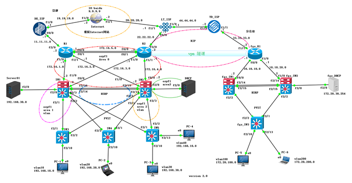
二、模拟环境说明:
软件:GNS3 2.19
镜像:
7200 c7200-ik9o3s-mz.123-22.bin 3640: c3640-ik9o3s-mz.124-25c.bin
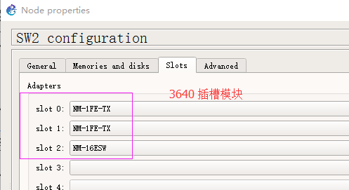
核心交换机、接入交换机、DHCP 服务器 用 3640 来模拟
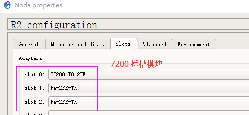
其他 路由器用 7200 模拟
运用到的知识有:
VLAN、Trunk、SPT(PVST)、VTP、DHCP 、HSRP、OSPF、RIP、NAT、端口映射、ACL、PBR、IPSec VPN、SLA。
三、总部网络配置步骤:
3.1、配置Trunk
SW1 SW2 配置相同
conf t
int r f2/1 -3
sw tr en d
sw m tr
exit
int r f2/14 -15
channel-group 1 mode on
exit
int port-channel 1
sw tr en d
sw m tr
exit
SW3 SW4 SW5 配置相同
conf t
no ip routing
int r f2/1 -2
sw tr en d
sw m tr
exit
3.2、配置VTP SW1、SW2 为Server ,其余为Client 域名:dfsc
密码:cisco 并在SW1 上面创建4 个vlan 10 20 30 40
SW1 SW2 配置相同
end
vlan d
vtp server
vtp domain dfsc
vtp pass cisco
vtp pru
exit
SW3 SW4 SW5 : VTP 配置
end
vlan d
vtp client
vtp domain dfsc
vtp pass cisco
exit
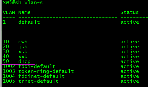
SW1 上面创建vlan ,查看在sw 2 sw3 sw4 sw5 有无自动动创建vlan 。
end
vlan d
vlan 10 name cwb
vlan 20 name jsb
vlan 30 name xsb
vlan 40 name xxb
vlan 50 name dhcp
exit
3.3、配置SVI接口,在SW1 SW2 上面配置
SW1:
conf t
int vlan 10
ip add 192.168.10.1 255.255.255.0
no sh
int vlan 20
ip add 192.168.20.1 255.255.255.0
no sh
int vlan 30
ip add 192.168.30.1 255.255.255.0
no sh
int vlan 40
ip add 192.168.30.1 255.255.255.0
no sh
ip add 192.168.40.1 255.255.255.0
int vlan 50
ip add 192.168.50.1 255.255.255.0
no sh
exit
SW2:
conf t
int vlan 10
ip add 192.168.10.2 255.255.255.0
no sh
int vlan 20
ip add 192.168.20.2 255.255.255.0
no sh
int vlan 30
ip add 192.168.30.2 255.255.255.0
no sh
int vlan 40
ip add 192.168.40.2 255.255.255.0
no sh
int vlan 50
ip add 192.168.50.2 255.255.255.0
no sh
exit
3.4、配置生成树协议,在SW1 SW2 上面配置
SW1 为 vlan 10 vlan 20 的根桥,vlan 30 vlan 40 备用根桥
SW2 为 vlan 30 vlan 40 的根桥,vlan 10 vlan 20 备用根桥
SW1:
conf t
spanning-tree vlan 10 root pri
spanning-tree vlan 20 root pri
spanning-tree vlan 30 root sec
spanning-tree vlan 40 root sec
exit
SW2:
conf t
spanning-tree vlan 30 root pri
spanning-tree vlan 40 root pri
spanning-tree vlan 10 root sec
spanning-tree vlan 20 root sec
exit
3.5、划分接口到相应的vlan
SW3:
conf t
int f2/10
sw m acc
sw acc vlan 10
no sh
span portfast
exit
SW4:
conf t
int f2/10
sw m acc
sw acc vlan 20
no sh
span portfast
exit
SW5:
conf t
int f2/10
sw m acc
sw acc vlan 30
no sh
span portfast
int f2/13
sw m acc
sw acc vlan 40
no sh
span portfast
exit
SW2:
conf t
int f2/0
sw m acc
sw acc vlan 50
no sh
exit
3.6、配置DHCP
3.6.1、先配置DHCP 的f2/0接口IP 并添加路由,本案例中DHCP是由路由器模拟的,生产环境中应该是一台真实服务器。
DHCP:
conf t
int f2/0
no sh
no sw
ip add 192.168.50.254 255.255.255.0
exit
ip route 0.0.0.0 0.0.0.0 f2/0
3.6.2、配置DHCP
DHCP:
conf t
service dhcp
ip dhcp excluded-address 192.168.10.1 192.168.10.10
ip dhcp excluded-address 192.168.20.1 192.168.20.10
ip dhcp excluded-address 192.168.30.1 192.168.30.10
ip dhcp excluded-address 192.168.40.1 192.168.40.10
ip dhcp pool vlan10
default-router 192.168.10.254
network 192.168.10.0
dns-server 8.8.8.8
ip dhcp pool vlan20
default-router 192.168.20.254
network 192.168.20.0
dns-server 8.8.8.8
ip dhcp pool vlan30
default-router 192.168.30.254
network 192.168.30.0
dns-server 8.8.8.8
ip dhcp pool vlan40
network 192.168.40.0
default-router 192.168.40.254
network 192.168.40.0
dns-server 8.8.8.8
exit
3.7、配置DHCP中继
SW1 SW2 :配置相同
conf t
int vlan 10
ip helper-address 192.168.50.254
int vlan 20
ip helper-address 192.168.50.254
int vlan 30
ip helper-address 192.168.50.254
int vlan 40
ip helper-address 192.168.50.254
exit
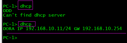
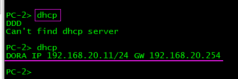
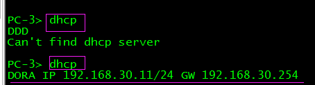
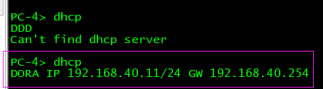
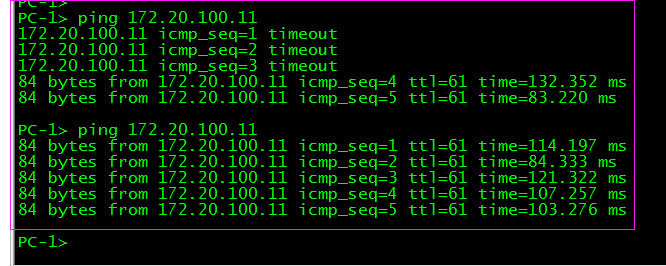
测试
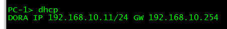
双击打开,pc-1 2 3 4 终端,输入dhcp
看是否能获取到IP
3.8、配置HSRP
SW1:
conf t
int vlan 10
standby 10 ip 192.168.10.254
standby 10 priority 105
standby 10 preempt
standby 10 track f1/0
exit
int vlan 20
standby 20 ip 192.168.20.254
standby 20 priority 105
standby 20 preempt
stand 20 track f1/0
exit
int vlan 30
standby 30 ip 192.168.30.254
standby 30 pre
exit
int vlan 40
standby 40 ip 192.168.40.254
standby 40 pre
exit
SW2:
conf t
int vlan 30
standby 30 ip 192.168.30.254
standby 30 priority 105
standby 30 preempt
standby 30 track f0/0
exit
int vlan 40
standby 40 ip 192.168.40.254
standby 40 priority 105
standby 40 preempt
standby 40 track f0/0
exit
int vlan 10
standby 10 ip 192.168.10.254
standby 10 pre
exit
int vlan 20
standby 20 ip 192.168.20.254
standby 20 pre
exit
3.9、配置R1、R2、SW1、SW2接口IP,以及链路捆绑地址。
3.9.1、路由器 R1 R2 接口IP 配置
R1:
conf t
int port-channel 1
ip add 172.16.5.1 255.255.255.0
exit
int r f0/0 -1
channel-group 1
no sh
exit
int f1/0
ip add 172.16.1.1 255.255.255.0
no sh
int f1/1
ip add 172.16.2.1 255.255.255.0
no sh
exit
R2:
conf t
int port-channel 1
ip add 172.16.5.2 255.255.255.0
exit
int r f0/0 -1
channel-group 1
no sh
exit
int f1/0
ip add 172.16.3.1 255.255.255.0
no sh
int f1/1
ip add 172.16.4.1 255.255.255.0
no sh
exit
3.9.2、三层交换机SW1 SW2 接口IP配置
SW1:
conf t
int f1/0
no sh
ip add 172.16.1.2 255.255.255.0
int f0/0
no sh
ip add 172.16.3.2 255.255.255.0
exit
SW2:
conf t
int f1/0
ip add 172.16.2.2 255.255.255.0
no sh
int f0/0
ip add 172.16.4.2 255.255.255.0
no sh
exit
3.10、OSPF配置 ,R1、R2、SW1、SW2启ospf 接口IP宣告到area 0,vlan的IP宣告到area 1,并把vlan设置为被动接口。
R1:
conf t
router ospf 1
router-id 1.1.1.1
net 172.16.1.0 0.0.0.255 a 0
net 172.16.2.0 0.0.0.255 a 0
net 172.16.5.0 0.0.0.255 a 0
exit
R2:
conf t
router ospf 1
router-id 2.2.2.2
net 172.16.3.0 0.0.0.255 a 0
net 172.16.4.0 0.0.0.255 a 0
net 172.16.5.0 0.0.0.255 a 0
exit
SW1:
conf t
router ospf 1
router-id 3.3.3.3
net 172.16.1.0 0.0.0.255 a 0
net 172.16.3.0 0.0.0.255 a 0
net 192.168.10.0 0.0.0.255 a 1
net 192.168.20.0 0.0.0.255 a 1
net 192.168.30.0 0.0.0.255 a 1
net 192.168.40.0 0.0.0.255 a 1
net 192.168.50.0 0.0.0.255 a 1
passive-interface vlan 10
passive-interface vlan 20
passive-interface vlan 30
passive-interface vlan 40
passive-interface vlan 50
exit
SW2:
conf t
router ospf 1
router-id 4.4.4.4
net 172.16.2.0 0.0.0.255 a 0
net 172.16.4.0 0.0.0.255 a 0
net 192.168.10.0 0.0.0.255 a 2
net 192.168.20.0 0.0.0.255 a 2
net 192.168.30.0 0.0.0.255 a 2
net 192.168.40.0 0.0.0.255 a 2
net 192.168.50.0 0.0.0.255 a 3
passive-interface vlan 10
passive-interface vlan 20
passive-interface vlan 30
passive-interface vlan 40
passive-interface vlan 50
exit
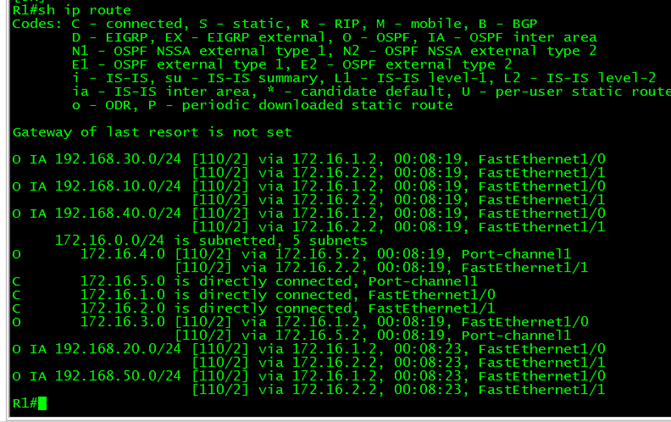
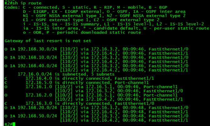
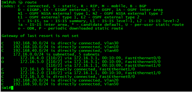
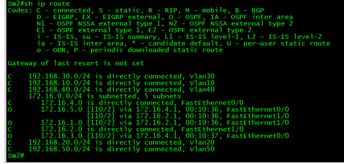
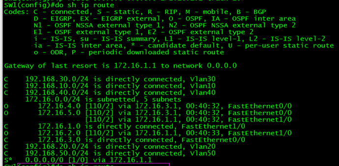
查看R1、R2 SW1 SW2路由表
3.11、配置R1、R2外网口地址
R1:
conf t
int f2/0
ip add 11.11.11.2 255.255.255.0
no sh
exit
DX_ISP:
conf t
int f0/0
no sh
ip add 11.11.11.1 255.255.255.0
exit
R2:
conf t
int f2/0
ip add 22.22.22.2 255.255.255.0
no sh
exit
LT_ISP:
conf t
int f0/0
ip add 22.22.22.1 255.255.255.0
no sh
exit
3.12、NAT配置
R1:
conf t
ip access-list standard nat
permit 192.168.0.0 0.0.255.255
exit
ip nat inside source list nat interface f2/0 overload
int f2/0
ip nat outside
exit
int f1/0
ip nat inside
int f1/1
ip nat inside
exit
int port-channel 1
ip nat inside
exit
R2:
conf t
ip access-list standard nat
permit 192.168.0.0 0.0.255.255
exit
ip nat inside source list nat interface f2/0 overload
int f2/0
ip nat outside
exit
int f1/0
ip nat inside
int f1/1
ip nat inside
exit
int port-channel 1
ip nat inside
exit
3.13、SW1、SW2、R1、R2添加默认路由,SW1优先走DX_ISP,当DX_ISP断掉后,就走LT_ISP这条链路,同样SW2 优先走LT_ISP,当LT_ISP断了后,走DX_ISP出去。
SW1:配置默认路由
conf t
ip route 0.0.0.0 0.0.0.0 172.16.1.1
ip route 0.0.0.0 0.0.0.0 172.16.3.1 5
SW2:配置默认路由
conf t
ip route 0.0.0.0 0.0.0.0 172.16.4.1
ip route 0.0.0.0 0.0.0.0 172.16.2.1 5
R1、R2添加默认路由,发往公网。
R1:R2 配置都一样
ip route 0.0.0.0 0.0.0.0 f2/0
3.14、route-map,配置策略路由。
R2:
conf t
ip access-list extended dx
permit ip any host 11.11.11.1
exit
route-map dx
match ip address dx
set ip next-hop 172.16.5.1
exit
int f1/0
ip policy route-map dx
int f1/1
ip policy route-map dx
exit
R1:
conf t
ip access-list extended lt
permit ip any host 22.22.22.1
exit
route-map lt
match ip address lt
set ip next-hop 172.16.5.2
exit
int f1/0
ip policy route-map lt
int f1/1
ip policy route-map lt
exi
四、分公司网络配置
4.1、配置Trunk
fgs_SW1 fgs_SW2 配置相同
conf t
int f2/2
sw tr en d
sw m tr
exit
int r f2/14 -15
channel-group 1 mode on
exit
int port-channel 1
sw tr en d
sw m tr
end
fgs_SW3:
conf t
no ip routing
int r f2/1 -2
sw tr en d
sw m tr
end
4.2、在fgs_SW1 、2、3 上面分别创建vlan 100 vlan 200 vlan 300 把fgs_SW2的 f2/0,划分到vlan 300 fgs_SW3 f2/10ààvlan100 f2/13àvlan 200
fgs_SW1、2、3 划分vlan 配置一样。(路由器创建vlan,是在特权模式。)
vlan d
vlan 100
vlan 200
vlan 300
exit
fgs_sw3把接口划分进vlan
conf t
int f2/10
sw m acc
sw acc vlan 100
no sh
int f2/13
sw m acc
sw acc vlan 200
no sh
end
fgs_SW2:
conf t
int f2/0
sw m acc
sw acc vlan 300
no sh
end
4.3、SVI接口配置
fgs_SW1:
conf t
int vlan 100
ip add 172.20.100.1 255.255.255.0
no sh
int vlan 200
ip add 172.20.200.1 255.255.255.0
no sh
int vlan 300
ip add 172.20.30.1 255.255.255.0
no sh
end
fgs_SW2:
conf t
int vlan 100
ip add 172.20.100.2 255.255.255.0
no sh
int vlan 200
ip add 172.20.200.2 255.255.255.0
no sh
int vlan 300
ip add 172.20.30.2 255.255.255.0
no sh
end
4.4、DHCP配置
fgs_dhcp:
conf t
ip routing
int f2/0
no sw
ip add 172.20.30.254 255.255.255.0
no sh
exit
ip dhcp excluded-address 172.20.100.1 172.20.100.10
ip dhcp excluded-address 172.20.200.1 172.20.200.10
ip dhcp pool vlan100
default-router 172.20.100.254
network 172.20.100.0 /24
dns-server 8.8.8.8
ip dhcp pool vlan200
default-router 172.20.200.254
network 172.20.200.0 /24
dns-server 8.8.8.8
exit
ip route 0.0.0.0 0.0.0.0 f2/0
DHCP中继配置:
fgs_SW1 fgs_SW2: 配置一样
conf t
int vlan 100
ip helper-address 172.20.30.254
int vlan 200
ip helper-address 172.20.30.254
exit
4.5、配置生成树
fgs_SW1:
spanning-tree vlan 100 root pr
spanning-tree vlan 200 root sec
fgs_SW2:
spanning-tree vlan 200 root pr
spanning-tree vlan 100 root sec
4.6、HSRP 配置
fgs_SW1:
conf t
int vlan 100
standby 100 ip 172.20.100.254
standby 100 priority 105
standby 100 preempt
standby 100 track f0/0
exit
int vlan 200
standby 200 ip 172.20.200.254
standby 200 pre
exit
fgs_SW2:
conf t
int vlan 100
standby 100 ip 172.20.100.254
standby 100 preempt
exit
int vlan 200
standby 200 ip 172.20.200.254
standby priority 105
standby 200 preempt
standby 200 track f1/0
exit
4.6、配置fgs_SW1 fgs_SW2 fgs_R1 接口IP,以及路由。
fgs_SW1:
conf t
int f0/0
no sh
ip add 10.10.10.2 255.255.255.0
exit
ip route 0.0.0.0 0.0.0.0 10.10.10.1
fgs_SW2:
conf t
int f1/0
ip add 10.10.20.2 255.255.255.0
no sh
exit
ip route 0.0.0.0 0.0.0.0 10.10.20.1
fgs_R1:
conf t
int f0/0
no sh
ip add 10.10.10.1 255.255.255.0
int f1/0
no sh
ip add 10.10.20.1 255.255.255.0
int f1/1
ip add 33.33.33.2 255.255.255.0
no sh
exit
ip route 0.0.0.0 0.0.0.0 33.33.33.1
ip route 172.20.0.0 255.255.0.0 10.10.10.2
ip route 172.20.0.0 255.255.0.0 10.10.20.2
4.7、NAT配置:
fgs_R1:
conf t
ip access-list standard nat
permit 172.20.0.0 0.0.255.255
exit
ip nat inside source list nat interface f1/1 overload
int f1/1
ip nat outside
exit
int f0/0
ip nat inside
int f1/0
ip nat inside
exit
4.8、配置YD_ISP LT_ISP 接口IP,以及动态路由协议,这里配置RIP ,用来模拟 分公司 公网IP 和总部公网IP,实现现实中的通信。YD_ISP:
conf t
int f1/1
ip add 33.33.33.1 255.255.255.0
no sh
int f1/0
ip add 44.44.44.2 255.255.255.0
no sh
exit
LT_ISP:
conf t
int f1/0
no sh
ip add 44.44.44.1 255.255.255.0
exit
RIP:配置
fgs_R1:
conf t
router rip
ver 2
no au
net 33.33.33.0
end
YD_ISP:
conf t
router rip
ver 2
no au
net 33.33.33.0
net 44.44.44.0
end
LT_ISP:
conf t
router rip
ver 2
no au
net 44.44.44.0
net 22.22.22.0
end
R2:
conf t
router rip
ver 2
no au
net 22.22.22.0
end
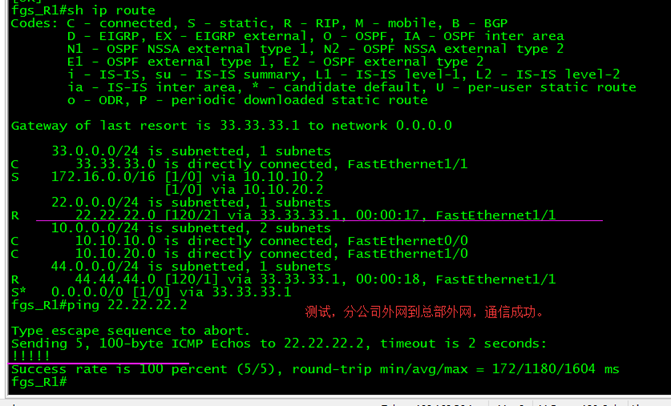
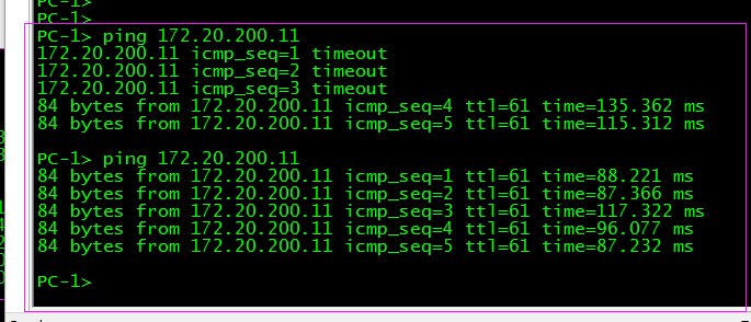
测试:分公司外网到总部外网能否正常通信。
4.9、再添加一台R,模拟Internet 访问
DX_ISP:配置
conf t
int f1/0
no sh
ip add 19.19.19.1 255.255.255.0
ip route 0.0.0.0 0.0.0.0 19.19.19.2
exit
Internet:
conf t
int f1/0
no sh
ip add 19.19.19.2 255.255.255.0
exit
int loopback 0
ip add 9.9.9.9 255.255.255.0
no sh
exit
ip route 11.11.11.0 255.255.255.0 19.19.19.1
int f1/1
ip add 20.20.20.2 255.255.255.0
no sh
exit
ip route 22.22.22.0 255.255.255.0 20.20.20.1
LT_ISP:
int f1/1
ip add 20.20.20.1 255.255.255.0
no sh
exit
ip route 0.0.0.0 0.0.0.0 20.20.20.2
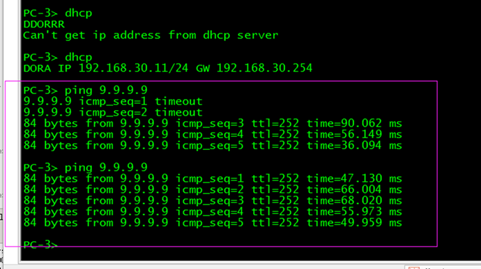
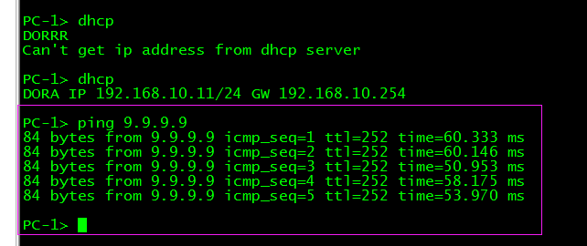
Internet 访问测试:
五、IPsec VPN配置
R2:
conf t
crypto ipsec transform-set vpnzb ah-sha-hmac esp-aes
exit
crypto isakmp policy 1
encryption aes
hash sha
authentication pre-share
group 5
lifetime 40000
exit
crypto isakmp key cisco123 address 33.33.33.2
access-list 101 permit ip 192.168.0.0 0.0.255.255 172.20.0.0 0.0.255.255
crypto map vpntu 1 ipsec-isakmp
set transform-set vpnzb
set peer 33.33.33.2
match address 101
exit
ip route 172.20.0.0 255.255.0.0 f2/0
int f2/0
crypto map vpntu
exit
fgs_R1:
conf t
crypto ipsec transform-set vpnfgs ah-sha-hmac esp-aes
exit
crypto isakmp policy 1
encryption aes
hash sha
authentication pre-share
group 5
lifetime 40000
exit
crypto isakmp key cisco123 address 22.22.22.2
access-list 101 permit ip 172.20.0.0 0.0.255.255 192.168.0.0 0.0.255.255
crypto map vpntu 1 ipsec-isakmp
set transform-set vpnfgs
set peer 22.22.22.2
match address 101
exit
ip route 192.168.0.0 255.255.0.0 f1/1
int f1/1
crypto map vpntu
exit
修改NAT的ACL
R2:(这里是为了不让192.168.0.0访问172.20.0.0的流量撞上NAT)
conf t
no ip access-list standard nat
ip access-list extended nat
deny ip 192.168.0.0 0.0.255.255 172.20.0.0 0.0.255.255
permit ip any any
exit
fgs_R1:
conf t
no ip access-list standard nat
ip access-list extended nat
deny ip 172.20.0.0 0.0.255.255 192.168.0.0 0.0.255.255
permit ip any any
exit
VPN测试:
六、服务器端口映射
Server01配置:
vlan d
vlan 30 name cwb
exit
conf t
int f2/8
no sh
no sw
ip add 192.168.30.8 255.255.255.0
exit
ip route 0.0.0.0 0.0.0.0 f2/8
user cisco pri 15 sec cisco
line vty 0 4
login local
exit
SW1:
conf t
int f2/8
no sh
sw m acc
sw acc vlan 30
exit
R1:
conf t
ip nat inside source static tcp 192.168.30.8 80 11.11.11.2 8080 extendable
R2:
conf t
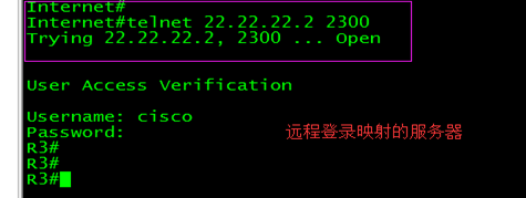
ip nat inside source static tcp 192.168.30.8 23 22.22.22.2 2300 extendable
查看映射
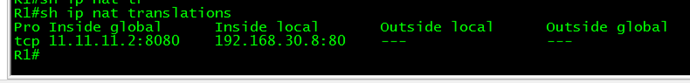
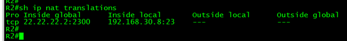
测试远程登录
_____________ End ___________________
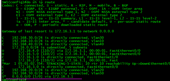
在现有的配置上,进一步完善优化,在 SW1 SW2 上面修改。
当R1(f1/0)、R2(f1/1) 的接口有问题,SW1、SW2线路切换。
SW1:
conf t
ip sla monitor 10
type echo protocol ipIcmpEcho 172.16.1.1 source-ipaddr 172.16.1.2
timeout 1000
frequency 3
exit
ip sla monitor schedule 10 life forever start-time now
track 10 rtr 10 reachability
exit
no ip route 0.0.0.0 0.0.0.0 172.16.1.1
ip route 0.0.0.0 0.0.0.0 172.16.1.1 track 10
测试浮动静态路由切换,当SW1检测到R1的172.16.1.1(f1/0)口不通时,自动把路由切换到备用的路由条目上。


把SW1 上面的vlan 10 vlan 20,再加上一个跟踪SW1的上行端口(R1的f1/0)地址的配置,当这个地址(172.16.1.1)不可达时,vlan 10的主,自动切换到SW2 。
int vlan 10
standby 10 track 10
exit


关掉R1的f1/0


 重新开启R1的f1/0


SW1(config-if)#int vlan 20
SW1(config-if)#standby 20 track 10
SW1(config-if)#exit
SW1(config)#
SW2:
conf t
ip sla monitor 20
type echo protocol ipIcmpEcho 172.16.4.1 source-ipaddr 172.16.4.2
timeout 1000
frequency 3
exit
ip sla monitor schedule 20 life forever start-time now
track 20 rtr 20 reachability
exit
no ip route 0.0.0.0 0.0.0.0 172.16.4.1
no ip route 0.0.0.0 0.0.0.0 172.16.2.1
ip route 0.0.0.0 0.0.0.0 172.16.4.1 track 20
ip route 0.0.0.0 0.0.0.0 172.16.2.1 5
int vlan 30
standby 30 track 20
int vlan 40
standby 40 track 20
exit
分公司的核心设备完善优化:
fgs_SW1:
conf t
ip sla monitor 100
type echo protocol ipIcmpEcho 10.10.10.1 source-ipaddr 10.10.10.2
timeout 1000
frequency 3
exit
ip sla monitor schedule 100 life forever start-time now
track 100 rtr 100 reachability
exit
int vlan 100
standby 100 track 100
exit
fgs_SW2:
ip sla monitor 200
type echo protocol ipIcmpEcho 10.10.10.1 source-ipaddr 10.10.10.2
timeout 1000
frequency 3
exit
ip sla monitor schedule 200 life forever start-time now
track 200 rtr 200 reachability
exit
int vlan 200
standby 200 track 200
exit
R2:
no ip route 172.20.0.0 255.255.0.0 f2/0
crypto map vpntu 1 ipsec-isakmp
reverse-route
exit
### reverse-route反向路由 RRI动态反向注入更细化静态路由,使数据那里进,那里出!会自动生成一条指向出口的路由。


fgs_R1:
no ip route 192.168.0.0 255.255.0.0 f1/1
crypto map vpntu 1 ipsec-isakmp
reverse-route
exit


SW1:
ip route 172.20.0.0 255.255.0.0 172.16.3.1
—————————————————————